FM Morse Code Keyer |
By N1HFX |
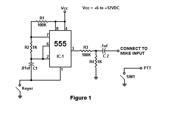
Many no code Technician class amateurs who are struggling to learn 5 WPM code simply do not have any avenue to get the necessary on the air practice. Figure 1 is a simple circuit which will generate a 700 Hz tone into any FM transceiver allowing an amateur to practice CW with another amateur on a 2 meter simplex frequency.
The circuit in Figure 1 is a simple tone oscillator using the famous type 555 timer chip. Resistors R1 and R2 form the timing circuit with Capacitor C1. Resistors R3 and R4 form a voltage divider network to reduce the output to microphone level. Capacitor C2 couples the output to the transceiver. SW1 is used to switch the transceiver into transmit mode prior to generating the tones. Connect your keyer as shown to pin 1 and the bottom of C1.
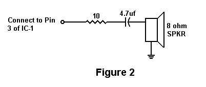
If connecting to an HT which shares the PTT with the microphone input, simply connect a 2.2K resistor in series with SW1. If your keyer does not have a sidetone, then use the speaker circuit in Figure 2.
Remember to switch your FM transceiver to a low power setting for those long key down periods while sending CW. Most FM transceivers are not designed to handle long key down periods at full power. Periodically check your rig while transmitting for possible overheating.
| R1,R3 | 100K Resistor | |
| R2,R4 | 1K Resistor | |
| C1 | .01 microfarad capacitor | |
| C2 | .1 microfarad capacitor | |
| IC-1 | Type 555 timer chip | |
| SW1 | Any SPST switch |

