An Inexpensive Tone Encoder
If your local repeater has got you singing the PL tone blues, then read on. For less than $10, an inexpensive PL tone generator can be constructed that will bring new life into that old non-PL rig.

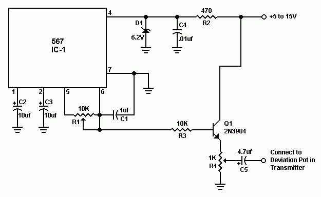
Figure 1 illustrates an easy circuit that can be constructed with mostly Radio Shack parts on any general purpose circuit board. The only rigid requirement is that capacitor C1 be stable over a wide temperature range. Use only Mylar, Polyester or Metal film for capacitor C1. The frequency is determined by the following formula:
FREQUENCY = 1/R1C1
The specified values should allow any tone between 100 to 300 Hz. Increase R1 or add another resistor in series with R1 for lower tone frequencies.
The output of this PL generator should be connected to the deviation potentiometer in the transmitter circuit and not the microphone input. (Check schematic diagram of transceiver.) If the circuit reduces the transmitter audio, install a resister between the output of the circuit and the transmitter. Use a value in the range of 1K to 10K depending on what yields the best results.
The heart of the PL tone generator is the ultra stable 567 IC which is readily available from JDR Microdevices or Ocean State Electronics. All other parts are available at Radio Shack.
To align the frequency of the tone generator, use another transceiver with CTCSS decode capability for the desired PL tone frequency. Attach a dummy load to the transmitter and key down the transmitter which turning R1. As soon as the correct frequency is obtained, the squelch will open on the transceiver with CTCSS decode. Now adjust R4 for the correct audio level of the tone. The tone level only needs to be loud enough for the other receiver to decode the tone and not loud enough for others to hear it. If the tone can be easily heard then the level is probably too high.
IC's are Available from JDR MicroDevices (1-800-538-5000) or
Ocean State Electronics. The author will make this chip available
to RASON members for about $1 each if enough inquiries are
received.
Parts List
| R1 | 10K 15 turn trimmer pot (271-343) |
| R2 | 470 ohm ¼ watt resistor |
| R3 | 10K ohm ¼ watt resistor |
| R4 | 1K ohm trimmer pot (271-280) |
| C1 | 1 uF Mylar, Polyester or Metal Film Capacitor (272-1055) |
| C2, C3 | 10 uF Electrolytic Capacitor (272-1025) |
| C4 | .01 uF ceramic Capacitor (272-131) |
| C5 | 4.7 uF Electrolytic Capacitor (272-1024) |
| D1 | 1N4735 6.2 volt Zener diode (276-561) |
| Q1 | 2N3904 or similar transistor (276-2016) |
73 - N1HFX